- 您现在的位置:买卖IC网 > Sheet目录1994 > DS2404B (Maxim Integrated Products)IC ECONORAM TIMECHIP 5.5V 16SSOP
DS2404
23 of 29
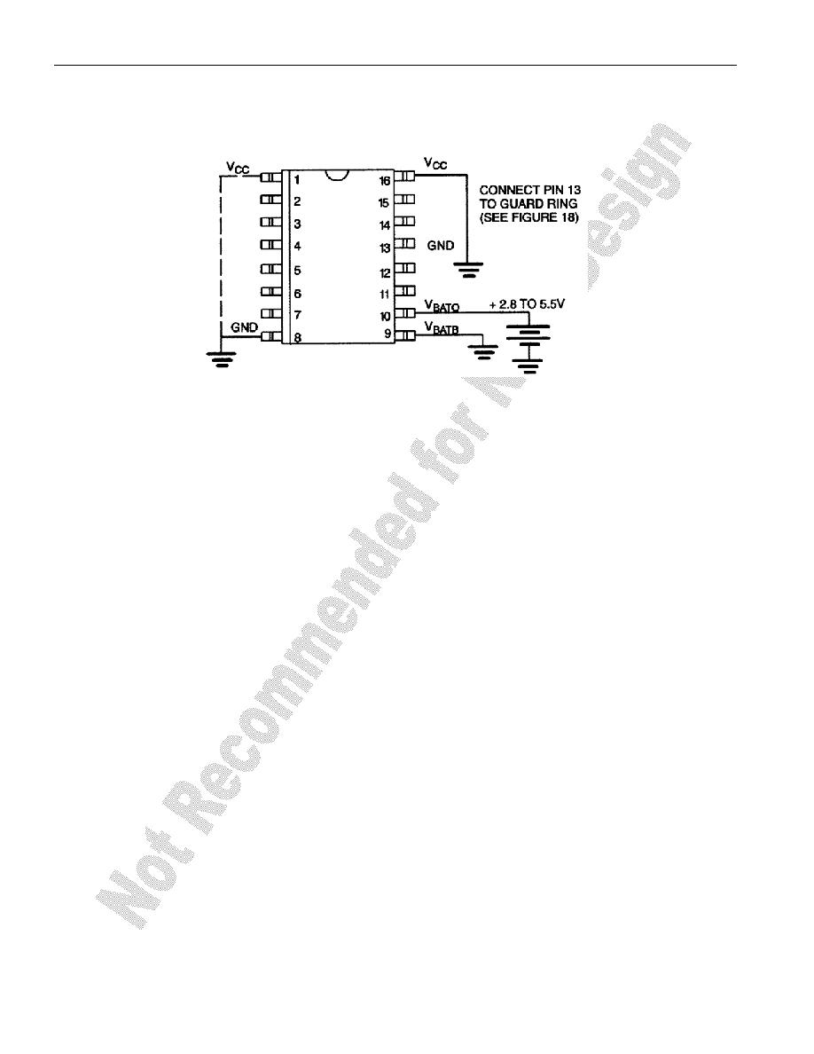
Battery Operate Mode
Figure 17 shows the necessary connections for operating the DS2404 in Battery Operate mode.
BATTERY OPERATE MODE Figure 17
VCC
Pin 1 & 16
Ground
VBATB
Pin 9
Ground
VBATO
Pin 10
2.8 to 5.5V
The VBATO pin is normally connected to any standard 3 V lithium cell or other energy source. The Battery
Operate mode also minimizes the power-consumption in applications where battery backup is not
required and the VBATO lead is directly connected to the system’s 5V supply.
NOTE:
In Battery Operate mode, the voltage on DQ must never exceed the voltage on VBATO if the 3-wire
interface is used. This restriction does not apply to the 1-Wire interface.
DEVICE OPERATION MODES
With its two ports and two power modes the DS2404 can be operated in several ways. While the
maximum voltage on the 1-Wire port (I/O) is always 6V, the maximum voltage on the 3-wire port (DQ)
depends on the power mode and actual operating voltage. A particular port is selected by setting the
control lines to a state that makes the other port inactive. See Table 1 for details.
When using the 3-wire port only and the DS2404 is wired for VCC Operate Mode (Battery Backed) the
1 Wire I/O pin can be used as counter input. This mode requires that the I/O lead is connected to VCC
through a 5k
Ω (typical) resistor. To enable communication through the 3-wire port a reset/presence
sequence has to be performed on the 1-Wire port after the system has powered up.
发布紧急采购,3分钟左右您将得到回复。
相关PDF资料
DS2415P+T&R
IC TIME CHIP 1-WIRE 6-TSOC
DS2417X/T&R
IC TIMECHIP W/INTRPT 1WIRE CSP
DS26502LN+
IC T1/E1/J1 64KCC ELEMENT 64LQFP
DS26503LN+
IC T1/E1/J1 BITS ELEMENT 64-LQFP
DS3105LN+
IC TIMING LINE CARD 64-LQFP
DS3106LN+
IC TIMING LINE CARD 64-LQFP
DS3231MZ+
IC RTC I2C 8SOIC
DS3231SN#T&R
IC RTC W/TCXO 16-SOIC
相关代理商/技术参数
DS2404B/T&R
制造商:Maxim Integrated Products 功能描述:ECONORAM/TIME, SSOP16-TRL (GENERIC) - Tape and Reel
DS2404B+
制造商:Maxim Integrated Products 功能描述:REAL TIME CLOCK SERL 512BYTE 16SSOP - Rail/Tube
DS2404B+T&R
制造商:Maxim Integrated Products 功能描述:REAL TIME CLOCK SERL 512BYTE 16SSOP - Tape and Reel
DS2404FP000
制造商:Thomas & Betts 功能描述:200A,CON,3P4W,MG,404,3P480V
DS2404FP000/DF2029
制造商:Thomas & Betts 功能描述:RS DS2404FP000/DF2029 200A,CON,3P4W
DS2404FP000/DF2032
制造商:Thomas & Betts 功能描述:200A,CON,3P4W,MG,404,3P480V,DF2032
DS2404FP00K
制造商:Thomas & Betts 功能描述:200A,CON,3P4W,MG,404,00K,3P480V
DS2404FPOOO/DF2029
制造商:Thomas & Betts 功能描述:RS DS2404FPOOO/DF2029 200A,CON,3P4W